Floor Plans
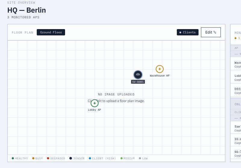
The Floor Plan screen places your access points and sensors on an actual image of your space, instead of just a list.
Viewing (everyone)
- Switch between floor tabs if you have multiple floors.
- See the uploaded plan image with AP pins (colored by status) and sensor pins.
- A scale indicator so distances on the plan correspond to real-world measurements.
- An optional live client-location overlay, showing roughly where connected devices currently are.
Editing (Admin)
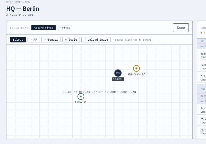
- Toolbar tools: Select, +AP, +Sensor, Scale, Upload Image.
- Drag pins to reposition APs/sensors — saved automatically.
- Click the canvas to place a new AP, or open a picker to place a sensor.
- Calibrate scale by clicking two points on the image and entering the real-world distance between them.
- Click an AP pin to open an inline panel for renaming it and assigning its BSSIDs.
- Double-click a floor tab to rename it; add or delete floors as needed.
If no image has been uploaded yet, a placeholder grid is shown so you can still position pins before adding the real plan.
Sensor displacement detection
The app watches whether a sensor's signal pattern still matches where it's pinned on the plan. If it drifts too far, a warning appears on the Site Overview screen naming the sensor and the floor, the RSSI deviation from its saved position, and — when there's enough surrounding AP data — an estimated new position on the plan. Drag the pin to its actual location in Edit mode to clear the warning.
Why it matters
Signal problems are often physical — a dead zone in one corner, a wall that blocks a signal, a sensor placed too far from what it's meant to monitor. Seeing devices laid out spatially makes those problems obvious in a way a table never will.